So, clearly I’m way into cyanotypes right now. But the process requires sunlight- and that’s not always feasible for me because I do a lot of my work at night. To make cyanotypes at home with a constant, reliable and controllable light source, I would need a UV light box.
Light boxes are priced in the thousands, even used ones can be quite expensive. There is a lot of information out there on how to build your own light box but most tutorials require bulbs. I wanted my light box to be as sleek and easy to build as possible. I discovered that a few people had successfully constructed light boxes with UV LED light strips.
There still isn’t a lot of information about this very specific topic out there so today I’m going to show you how I constructed my LED UV light box.WARNING: this process requires the use of a soldering iron and some electrical wiring. If you’re going to attempt to make a box like this one and you don’t know how to solder or anything about electrical wiring please get help from a pro.
If you are seriously serious about building a light box like this, please visit the following links. This thread on LargeFormatPhotography.info gives a general breakdown of how the box is made and this post on Greg Brophy‘s blog goes into much more detail. These are the sources I used to build my light box.
MATERIALS:
- Two 20×24″ wooden boards
- Two 4×24″ wooden planks
- One 4×20″ wooden plank
- Two reels of 5 meter 5050 LED UV lights 300 SMD 12V DC
- 12 gauge speaker cable
- 20 gauge copper wire
- Soldering iron and solder
- Power supply box
- Power cord
- Hammer and nails

I started with two 20×24 wooden boards, two 4×24 wood planks and one 4×20 plank. All of these were purchased from my local hardware store for like, $25. I sanded them all really well and made sure they were clean.

I took one of the 20×24 wood boards and measured in 2 inches all the way around. This created a 16×20 rectangle (the size of prints that I will be making). On the two shorter sides of the board I drilled a hole at the middle point on each side where I would later run the speaker cable through.

Next, I applied my LED light strips! I cut the strips so that they fit in my 16×20 rectangle in a staggered pattern shown above. When cutting the LED strips you have to make sure to cut between the copper pads, there is a tiny image of scissors on the strip to show where you can cut. Each copper plate has a + or a – next to it, it is very important to make sure they are all placed uniformly on the board. Just make sure when you are laying the strips on the board that all of the + signs are on the bottom. The LED strips have tape on the back so they stick easily to the wood. I accidentally bought the strips that came with the water protective coating on top. I had to pull it back and cut off a little to expose the copper plates for soldering.


I’ve got two pictures for this next part. I stripped two separate 3 foot sections of the 12 gauge speaker cable (including the red and black wires that are inside the white one) and ran it through the hols I drilled earlier. I made the black and red wires run in opposite directions (it doesn’t matter which way they go) and stapled them down to the board.
This next part got intense! I cut the 20 gauge copper wire into short pieces and used them to bridge the LED copper plates to the wires that were stapled on the sides. You can see them in the picture above. On the left side of the board, I soldered the little copper pieces to the – copper plate on the LED lights and on the right side I soldered them to the + plate. Then I soldered the tiny wires to the big speaker cable wires I stapled down earlier. Basically, this made the large speaker cable on the left side of my board carry the negative charge and the right side carry the positive charge.
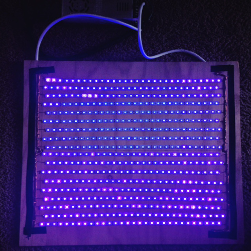
At this point I wanted to see if all of my connecting and soldering was a success! I grabbed my power supply box and power cord. I connected my – and + speaker cables from the board to the – and + segments on the power supply box. Then I connected the power cord to the the power supply by matching the wires in the power cord to their respective segments on the power supply box: black is live, white is neutral and green is ground.
I plugged it in and and POW! it all worked!!!! So, that’s pretty much the hard part. The rest was a cake walk.
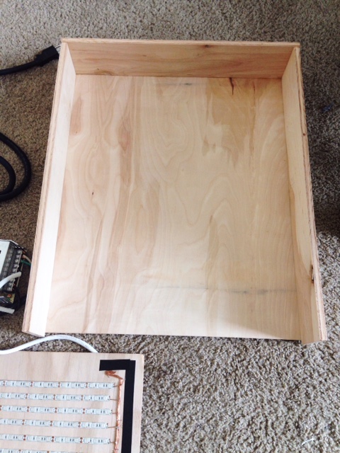
I took my other 20×24 board and hammered the 4×20, and two 4×24’s to it to create a three sided box.

So, at this point this is what my set up looked like.

Then I hammered the top of the box on so that the LED lights were the ceiling of the inside of the box. I left one of the short sides open so that I can slide my prints in and out easily. Later I will create a door to cover it, but for now this is cool.

Inside my UV LED light box!

This was a really fun project and I’m very please with how it came out. Hope you enjoyed seeing how I constructed my light box, comment if you have any questions or suggestion!


